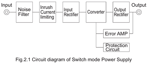
Switching power‑supply topologies are classified according to the circuit configuration of the DC‑DC converter section, which converts DC to high‑frequency AC and then back to DC.
These topologies include two types of oscillation methods: self‑excited, in which the converter oscillates by itself, and externally excited, in which an external oscillator is used. Control ICs for switching power supplies generally employ the externally excited method.
In self‑excited converters, the operating frequency varies with the input voltage and load conditions, whereas externally excited converters operate at a fixed frequency.
**Furthermore, forward and flyback topologies differ in how energy is transferred from the primary side to the secondary side.
(1) Forward converter
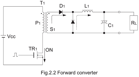
The single‑ended forward converter is one of the most commonly used topologies due to its simple circuit configuration and stable controllability.
Today, the externally excited (driven) type is predominant and is widely used across a broad power range, from low power up to approximately 1.5 kW.
When the switching transistor (TR) turns ON, diode D1 conducts and delivers current to the load. When the TR turns OFF, the energy stored in the choke coil is supplied to the load through diode D2.
(2) Push-pull converter
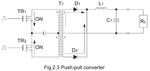
This topology uses two transistors (TRs) that are switched ON alternately.
When both TRs are OFF, diodes D1 and D2 conduct, supplying to the load the energy stored in the choke coil.
Because any imbalance in the ON durations of the alternating drive can cause DC magnetization of the transformer, this topology is not widely used.
(3) Half-bridge converter
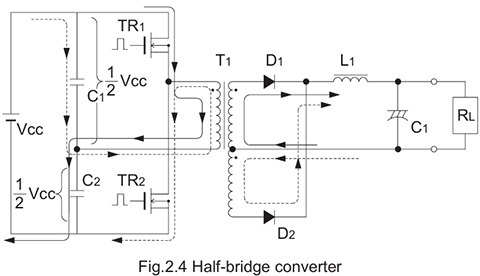
Although its operating principle is the same as that of a push–pull topology, this circuit uses only a single transformer winding, resulting in higher transformer utilization.
In addition, capacitors C1 and C2 prevent DC magnetization.
As a result, the voltage applied to the transformer is Vcc/2, while the transistors see the full Vcc, allowing the use of lower‑voltage‑rated transistors
(4) Full-bridge converter
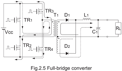
In this topology, TR1 and TR4, and TR2 and TR3, turn on alternately.
Both the transformer and the transistors experience a voltage of Vcc.
This configuration is particularly used in high‑power converters.
(5) Flyback converter
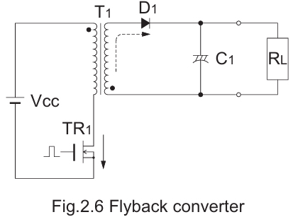
The single‑ended flyback topology is not suitable for high‑power applications, but it is widely used in low‑power switching power supplies because it can be implemented with a minimum number of components.
In this topology, when TR1 turns on, energy is stored in the transformer, and when TR1 turns off, the stored energy is delivered to the load through D1.
During the on‑time, the load is powered by the discharge of C1, which is why a larger‑capacity capacitor is required compared with the forward topology.
(6) Buck regulator
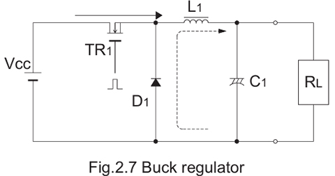
In buck regulators, the output voltage will be of the same polarity but always lower than the input voltage. One supply line must be common to both input and output. This may be either the positive or negative line, depending on the regulator design.
(7) Boost regulator
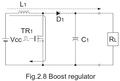
In boost regulators, the output voltage will be of the same polarity but always higher than the input voltage. One supply line must be common to both input and output. This may be either the positive or negative line, depending on the design.
(8) Buck-boost regulator
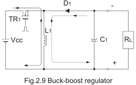
This topology operates in the same manner as a flyback converter.
Unlike the boost configuration, the positions of the transistor and the choke coil are reversed, so when TR1 turns off, a negative voltage appears at the output.
This topology is also referred to as the buck‑boost type.