(1) Input voltage range
This indicates the nominal input voltage, or the voltage range, within which all specifications are guaranteed.
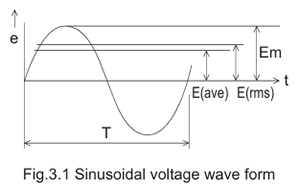
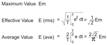
For AC input, the value is given as the RMS voltage. For DC input, however, the value includes its varying components.
Therefore, when the DC input contains ripple components, both the minimum and maximum voltages must be taken into account.
(2) Input current of SMPS
The input current flowing into the power supply is expressed as an RMS value.
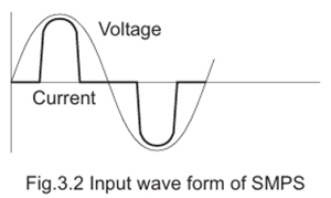
The current waveform differs depending on whether the unit uses an active filter method or a capacitor‑input method.
With an active filter, the input current waveform becomes close to a sine wave, similar to the input voltage.
In contrast, with a capacitor‑input method, the current flows only near the peak of the sine wave, as shown below.

(3) Input Power
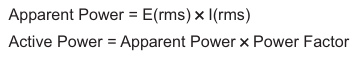
It can be seen that the input voltage is only slightly distorted by the very non-linear load presented by the capacitor input filter. The sinusoidal input is maintained because the line input resistance is very low. The input current however, is very distorted and discontinuous, but superficially would appear to be a part sine wave in phase with the voltage. This leads to a common error: The product V in (rms) x I in (rms) is assumed to give input power. This is not so! The product is the input volt-ampere product; it must be multiplied by the power factor (typically 0.6 for a capacitor input filter) to get true power.
The reason for the low power factor is that the nonsinusoidal current wave form contains a large odd harmonic content, and the phase and amplitude of all harmonics must be included in the measurement.
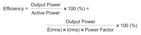
(4) Efficiency
Efficiency is defined as the ratio of output power to the active input power.
The specified efficiency is typically given at the rated output power, and efficiency decreases as the output current is reduced.
(5) Inrush current
Inrush current refers to the peak current that flows momentarily when the input voltage is applied to a switching power supply, exceeding the normal operating current.
At the input stage of a switching power supply, a large smoothing capacitor is installed, and a high current flows as this capacitor is charged rapidly at power‑on.
To reduce this inrush current, switching power supplies are equipped with an inrush‑current limiting circuit that suppresses the initial surge.
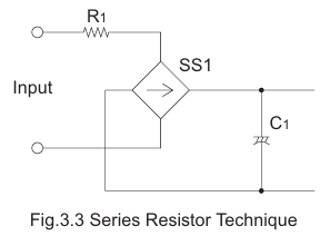
a. The Series Resistor Technique
There are two methods: inserting a resistor into the input line, or using the resistance component of the line filter coil.Because these methods introduce continuous power loss, they are mainly used for low-power applications.
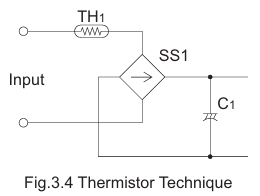
b. The Thermistor Technique
This method inserts a thermistor in the input line to suppress inrush current.
The thermistor has a high resistance at power‑up, limiting the inrush current, and its resistance decreases as it heats up during operation.
This characteristic helps minimize power loss during normal operation.
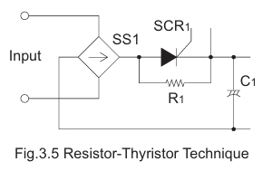
c. The Resistor-Thyristor Technique
In high‑power converters, it is effective to bypass (short‑circuit) the inrush‑current limiting device after start-up in order to reduce losses during normal operation.
Typically, resistor R1 is used as the start‑up resistor, and a single triac or relay is employed to switch it.
As shown in Fig. 3.5, after the unit starts up, R1 is shorted by the triac or relay, thereby bypassing the limiting circuit.
Although Fig. 3.5 illustrates an active inrush‑current limiting method in which the resistor is shorted by a triac, other configurations using thyristors or relays are also possible.
At power‑on, the inrush current is limited by R1.
Once the input capacitors become fully charged, the active shunt device operates to short‑circuit R1, reducing losses during normal operation.
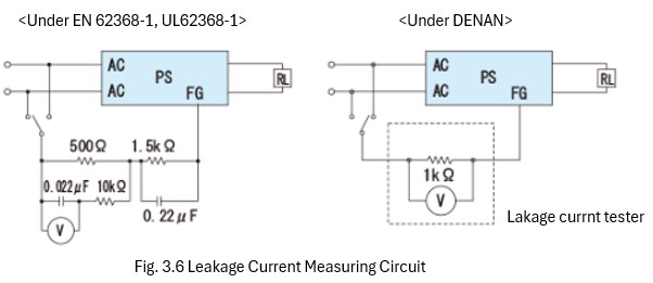
(6) Safety Leakage Current
This current is specified by various national safety standards to prevent electric shock and ensure user safety.
It refers to the current that flows to earth through paths such as the components on the primary side, the parasitic capacitance between the primary and secondary windings of the transformer, or the grounding capacitors in the noise filter.
Measurements are performed using the methods shown below. Additionally, under the Electrical Appliance and Material Safety Act (Japan), allowable current values vary depending on the frequency, so caution is required.
(7) Output Voltage
The nominal value of the DC voltage at the output terminals of a power supply.
(8) Rated Output Current
The maximum load current that a power supply is designed to provide at the specified ambient temperature.
Because the rating may change depending on the ambient temperature and cooling method, please refer to the derating characteristics.
(9) Minimum Load
Minimum output current required for voltages to be in specified range. Generally in multiple output power supplies, a minimum load is required on the main output to ensure regulation of auxiliary outputs.
(10) Line Regulation
The change in output voltage as the input voltage is varied over its specified limits, with load and temperature constant.
(11) Load Regulation
The change in output voltage as the load is varied from minimum to maximum, with line voltage and temperature held constant
(12) Overshoot
A transient change in output voltage that exceeds the specified accuracy limits. It may occur when a power supply is turned ON or OFF, or when there is a step change in line or load.
(13) Ripple and Noise
The amplitude of AC voltage present at the output of a power supply, expressed in millivolts peak‑to‑peak within a specified bandwidth. It results from feedthrough of rectified line frequency components, internal switching transients, and other random noise sources.
(14) Temperature Regulation
The change in output voltage (mV) due to variations in ambient temperature over a specified temperature range.
(15) Drift
This refers to the change in output voltage of a power supply over a specified period of time after a warm‑up period, with all other operating parameters—such as line, load, and ambient temperature—held constant.
(16) Start-up Time (Turn-on Delay Time)
The time in seconds after switch‑on for the output voltages to reach their nominal values within regulation limits.
(17) Hold-up Time
The time during which a power supply’s output voltage remains within specification following the loss of input power.
(18) Output Voltage Adjustment Range
The range over which the output voltage can be adjusted (and the means of adjustment).
(19) Overcurrent Protection
A protection feature that limits the output current to a predetermined value to prevent damage to the power supply or load during an overcurrent condition. The supply automatically returns to normal operation once the overcurrent is removed.
(20) Overvoltage Protection
A circuit that detects output overvoltages above a specified level and shuts down the converter to protect the load.
(21) Remote Sensing
This function is used when the distance between the power supply and the load is long and the voltage drop in the wiring cannot be ignored.
Remote sensing allows the power supply to maintain the voltage at the load point where the sensing leads are connected.
However, when using remote sensing, various precautions must be observed to prevent malfunctions or problems caused by incorrect wiring or disconnection of the sensing leads.
For details, please refer to the “Precautions for Use.”
(22) Remote ON/OFF
This function allows the output of the power supply to be turned ON and OFF by an external signal. It can be driven by relay contacts, transistors, or ICs.
It is also used when multiple power supplies are employed and a time delay is required between their start-up or shutdown sequences.
Note that some models operate with LOW for ON and HIGH for OFF, while others operate in the opposite manner. Please check the specifications before use.
(23) Isolation
Electrical isolation between the input and output of a power supply is provided by the power transformer.
The isolation resistance—typically specified in megohms—depends on the materials and clearances used throughout the power supply.
Isolation is also defined by the maximum AC or DC voltage that can be applied between the input, output, and/or chassis without breakdown.
(24) Operating Temperature
This indicates the ambient temperature range in which the power supply specifications are guaranteed.
For detailed derating conditions, please refer to the instruction manual for each model.
For models equipped with an internal forced‑air cooling fan, the ambient temperature is defined as the temperature of the incoming air.
Ambient temperature is measured at a point located 5 to 10 cm from the side of the power supply.
The measurement point must be located where it is not affected by radiant heat from the power supply or by convection of heated air.
(25) Operating Humidity
This indicates the ambient humidity range within which the power supply’s specifications are guaranteed during operation.
(26) Operating Altitude
The altitude at which a power supply can be operated safely. Expressed in m (feet).
(27) Storage Temperature
The range of ambient temperatures over which a converter may be stored long‑term without damage, expressed in ℃.
(28) Storage Humidity
The range of ambient relative humidity over which a converter may be stored long‑term without damage, expressed as a percentage (%).
(29) Storage Altitude
The altitude at which a power supply may be stored long‑term without damage, expressed in meters (feet).
(30) Vibration Standards
Defines the level of mechanical vibration (acceleration) the converter can withstand without damage.
(31) Impact Standards
Definition of acceleration of mechanical impact that can be applied to the converter without damage.