(1) Input voltage
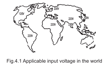
a. Applicable voltage in the world
Confirm the AC power supply voltage, frequency, and phase, as these may vary by region. Applying a voltage higher than the specified rating may damage the power supply. If the input voltage contains significant distortion, the unit may fail to operate properly or its service life may be reduced.
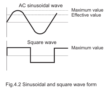
b. Applying square wave
A sinusoidal AC waveform is expressed as an RMS value, while a square waveform is expressed as its peak value.
A switching power supply rectifies and smooths the input voltage to generate a DC voltage close to the peak value, which is then used to operate the inverter stage.
Therefore, when a square-wave input is used, the applied voltage must be approximately 1.4 times the specified input rating.
If the indicated peak voltage is applied as-is, the unit may fail to operate properly, or even if it does operate, its service life may be significantly reduced.
If you have any questions regarding the use of square-wave input, please contact us in advance.
c. Influence of line filter or choke coil
If a line filter or choke coil with high inductance is installed on the input side, a back electromotive force may be generated when the input is switched on. This can cause an excessive voltage to be applied to the power supply and may result in damage or overstress.

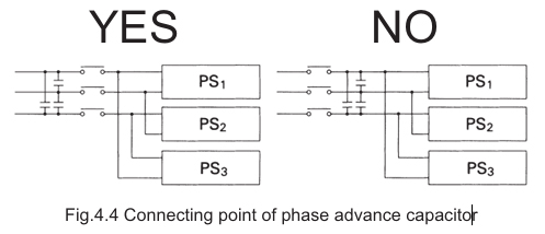
d. Influence of a phase advance capacitor
In three-phase AC systems, power-factor correction capacitors are used to compensate for current phase lag. However, if a power-factor correction capacitor is installed downstream of the input switch, the voltage stored in the capacitor when the switch is turned OFF may remain. When the switch is subsequently turned ON, this residual voltage can be superimposed on the input voltage, resulting in an excessive voltage. This may cause severe damage to the power supply. Therefore, installing a power-factor correction capacitor after the input switch must be strictly avoided.
(2) Auto ranging input power supply
For power supplies with an automatic input‑voltage selection function (100 V / 200 V), the input voltage is determined by detecting the peak value. Therefore, square‑wave input or DC input must never be applied.
(3) Input Power
Power supplies that do not comply with harmonic current regulations typically use a capacitor‑input rectifier and smoothing circuit at the input stage.
As a result, a distorted current waveform flows into the power supply, and the power factor generally falls in the range of 0.5 to 0.7.
Care is required when determining the capacity of the distribution panel, and when installing a transformer on the upstream side.

Note: I is thus the calculated ”real” component of input current (the component which produces the real power). Because of the large harmonic component in the distorted input current, the measured input rms current will be larger by an amount defined by the power factor P (approximately 0.5- 0.7) in the case of a capacitor input filter.
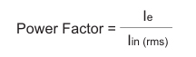
Note: Although Power Factor is normally defined as
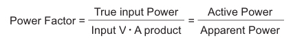
In the case of the ”direct-off-line” rectifier capacitor input filter, the low source resistance of the supply ensures that the input voltage remains near constant and free of distortion. Hence the power factor may be defined as the ratio of the effective input current to the rms input current, i.e.,
(4) Selecting fuses
A fuse is required on the input side of the power supply for safety. There are two types of fuses used in power supplies: built‑in fuses and external fuses.
a. Built‑in Fuse Type
No external fuse is required.
If the built‑in fuse blows, it usually indicates a failure inside the power supply, and replacing the fuse alone will not restore normal operation.
b. External Fuse Type
An external fuse must be properly installed.
The fuse must not blow due to inrush current and must also comply with the requirements of the relevant safety standards.
For details on fuse selection, please refer to the instruction manual and the application manual.
(5) Selecting switches
When selecting a switch, it is necessary to check both the inrush capacity and the continuous current capacity.
a. Inrush Capacity
When the power supply is turned on, an inrush current flows.
Therefore, the switch must have sufficient inrush capacity to withstand this surge current.
If the allowable rating is exceeded, the contacts may weld together, causing the switch to remain permanently in the ON state.
Switches may either specify the allowable inrush capacity directly, or specify how many times the continuous current rating can be tolerated as inrush current.
b. Continuous Current Capacity
The continuous current capacity indicates the level of current the switch can withstand continuously after the power has been turned on.
A switch must be selected such that it can safely handle the rated operating current.
(6) Lightning transients
Various surge voltages can appear on the input line, but lightning surges are the most significant because they carry very large energy and are a major cause of failures in electronic equipment.
In fact, many power-related failures observed in the field are caused by lightning surges, making proper protection essential.
Lightning surges are generally classified into the following three types.
| Direct Lightning Strike | This refers to a situation in which lightning strikes a power line or equipment directly. Because the energy of a direct lightning strike is extremely large, it is almost impossible to protect electronic devices by themselves. Therefore, buildings and facilities must be equipped with external lightning protection systems—such as lightning rods and grounding systems—to safely conduct the lightning current into the ground. |
|---|---|
| Induced Lightning | This type of surge occurs when lightning strikes near power lines or wiring. The surge voltage is induced by several mechanisms: ・Electromagnetic induction caused by the sudden change in the electromagnetic field during a lightning strike ・Electrostatic induction from the leader discharge of lightning Charge imbalance between the thundercloud and the power line, which collapses during a discharge and propagates as a surge These are the most common lightning surges that affect electronic equipment, and proper countermeasures are especially important. |
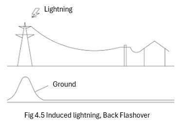
| Back Flashover | This type of surge occurs when lightning strikes the grounding wire or the transmission tower of a power line. Because the ground has impedance, the ground potential around the strike point rises sharply, and this elevated potential travels through the power line to the input side of connected equipment. This kind of surge occurs fairly often in the field, making protective devices especially important. |
Lightning surges occur more strongly between the line and ground than between lines.
1. Surges between lines
Surges between lines are usually small.
Switching power supplies have large input capacitors, which absorb these surges and reduce the impact
on the internal circuits.
2. Surges between line and ground
Line‑to‑ground surges are much larger.
Grounded equipment is designed to send surge current to ground, but lightning rises very quickly,
so wiring inductance becomes significant.
Because of this, even grounded equipment must be treated carefully, similar to ungrounded equipment.
3. Ungrounded equipment
In ungrounded equipment, surge voltage flows to ground through stray capacitance.
If this surge current passes through sensitive parts (such as ICs), it can cause failure.
Therefore, the chassis or metal case should be used to provide a bypass path so the surge does not flow
through weak components.
4. Environmental considerations
Lightning strength and frequency depend on the region and terrain.
Protection levels must match the installation environment.
Outdoor equipment especially requires full protection, including power cables and external cables.
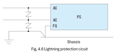
5. Protection methods
Arresters and surge absorbers can protect against induced surges and back‑flashover.
Line filters also help by smoothing the steep rise of lightning surge waveforms.
Characteristics of Each Surge Absorber
a. Discharge-type surge absorbers
Discharge-type surge absorbers offer high safety even when large energy surges exceeding their allowable limits are applied.However, they have the following characteristics:
・The discharge starting voltage and the discharge sustaining voltage are different
(i.e., they exhibit a holding characteristic).
・Their response speed is relatively slow, so a high voltage may be applied momentarily
before they start to operate.
For these reasons, they are effective against large surge events but are not suitable for fine or low-level surge protection.
b. Zinc-oxide varistors (MOVs) and bidirectional Zener diodes (TVS diodes)
These components have the following characteristics:
・They respond extremely quickly and can reliably protect equipment from steep,
fast-rising surge voltages such as lightning surges.
・When energy exceeding their rating is applied, they fail in a short-circuit mode,
thereby preventing further damage to the equipment.
Therefore, they are widely used as secondary protection devices in electronic equipment.
(7) Loads that prevent the power supply from starting up
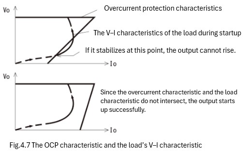
When using loads such as lamps or constant‑current loads, a power supply with a “fold‑back” type overcurrent protection characteristic may fail to start up.
This occurs because the load’s V‑I trajectory, from the moment voltage is applied until it reaches its normal operating point, settles on the fold‑back overcurrent protection curve, preventing the output from rising.
For this reason, the characteristics of such loads should be taken into account during the design or selection of the power supply.
In most cases, switching to a power supply with a rectangular (inverse‑L) overcurrent protection characteristic will resolve the issue.
(8) Peak loading
a) The current flows for more than several milliseconds
Current may be drawn up to the operating point of the overcurrent protection circuit.
However, frequent operation at this level may result in excessive heating of the power supply, potentially leading to failure; therefore, such use should be avoided.
If the operating current of the overcurrent protection circuit is insufficient for the intended application, the required peak current may be supported through a minor design modification.
For additional information or technical consultation, please contact our support team.
b) The current flows for several microseconds to several milliseconds
A capacitor may be added to the output to allow the required current to flow.
Please determine the capacitance of the additional output capacitor using the following formula.
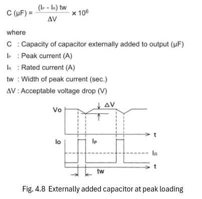
Please ensure that the capacitor’s allowable ripple current is checked when selecting or using an external capacitor.
If the capacitance of the external capacitor is excessively large, startup failure may occur. Since the maximum allowable capacitance varies depending on the model, please contact us for detailed specifications.
In addition, depending on the pulse characteristics of the load, the power supply unit may generate audible noise. Therefore, prior verification is recommended.
(9) Derating
The allowable output current varies depending on the ambient operating temperature and the mounting conditions.
Please ensure that the power supply is used within the derating range specified for each product.
If derating is applied to reduce the failure rate or to extend the service life of the power supply, please refer to the section titled “Reliability” for further information.
(10) Series Operation
When connecting multiple power supplies in series, there are generally two possible circuit configurations. The configuration shown in Figure a poses no issues; however, the configuration shown in Figure b requires caution.
In the case of Figure b, differences in the startup time or shutdown time of each power supply may cause the current from one unit to flow into the other. As a result, the power supplies may fail to start up correctly.
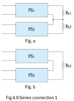
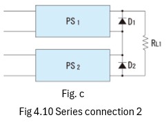
The applicability of series operation is described in the instruction manual for each product. Please check the relevant documentation before use. However, even for models that do not support series operation, it may be possible to operate them in series by inserting diodes on the output side, as shown in the figure below.
In this case, the diode used must satisfy the following two conditions:
・The forward voltage must be lower than that of the internal rectifier in the power supply.
・The diode must be rated to carry the full current of one power supply instantaneously.
Please be sure to select a diode that meets both requirements.
(11) Parallel Operation
1. Parallel Operation (for power supplies without a parallel‑operation function)
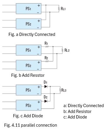
a. Case (Parallel connection of power supplies PS1 and PS2)
Because there is always a slight difference between the output voltages of PS1 and PS2, current will initially flow only from the power supply with the higher output voltage. As a result, the overcurrent protection circuit of that power supply operates and its output voltage decreases. Consequently, current then begins to flow from the other power supply with the lower output voltage.
In this situation:
One power supply enters an overcurrent condition (Io1)
The other power supply supplies the remaining current, Io2 = Io − Io1
This operating condition places one power supply in an overcurrent state, creating significant thermal and electrical stress. Such usage increases the failure rate and shortens the service life of the power supply, and is therefore not recommended. However, it may be possible to support this application by using a minor‑modified version in which the overcurrent protection threshold is set lower than the rated current.
Please contact us if you require such an option.
b. Case (Current balancing using output resistors)
In this method, resistors are added to the outputs to balance the output current of the two power supplies.
The resistance value should be determined based on:
The desired degree of current balance
The allowable power dissipation of the resistor
c. Case (Current balancing using diode characteristics)
This method balances the output current of the two power supplies by utilizing the slope of the diode’s forward voltage–current characteristic. When using this method, please ensure that the diode’s voltage rating, power dissipation, and heat dissipation are properly considered.
Note
For methods b and c, the actual current balance may vary depending on the output voltage difference between the power supplies and the load conditions.
2. Parallel Operation (for power supplies equipped with a parallel operation function)
Power supplies equipped with current balance (CB) terminals for parallel operation can be connected in parallel directly at the output. In such configurations, the internal parallel operation circuitry automatically balances the output current between the connected power supplies.
For further details, please refer to the individual instruction manuals for each model.
3. Redundant operation
By using the connection shown in Figure 5.12(c), redundant operation becomes possible, provided that the load current (the current flowing through RL3) is kept below the rated current of a single power supply.
In this configuration, if one power supply fails, the remaining unit can continue to operate as a backup.
(12) Remote sensing
a. Response speed
Using remote sensing may reduce the response speed due to the increased impedance of the sensing lines.
As a result, dynamic load regulation may deteriorate.
For this reason, it is recommended to arrange the power supply and wiring so that remote sensing is not required whenever possible.
b. Effect of noise
Because sensing lines have high impedance, they are susceptible to interference from surrounding circuits and wiring.
To avoid this, use twisted‑pair or shielded cables for the sensing lines, and route them away from high‑current paths and wiring that may generate noise.
c. Instability in Operation
If the sensing lines are extended, the power supply may operate unstably.
In such cases, please add capacitors at the sensing point, as well as between +V and +S, and between −V and −S.
For the capacitor used at the sensing point, an electrolytic capacitor should be used.
Using high‑Q film capacitors or ceramic capacitors may cause malfunction or unstable operation.
(13) Remote ON/OFF
Remote control allows the output of the power supply to be turned ON and OFF by an external signal while the main input wiring remains connected.
Various control methods are available, including application of an external voltage, external switching, and communication-based control.
Please refer to the instruction manual for each product for detailed specifications.
Since the voltage and current at the remote-control terminals are very small, low‑signal contacts should be used when switching the output ON and OFF by mechanical contact.
Additionally, ensure that load current does not flow into the remote‑control wiring, as this may cause malfunction.
*For products whose remote‑control option is marked “External driving power required,” an external power source must be supplied to drive the remote‑control circuit.
The power supply will turn ON when this external voltage is applied.
(14) Installation
a. When mounting to an enclosure
Mount the unit to a location on the enclosure that has sufficient mechanical strength.
During transportation, vibration may cause the enclosure to flex like a bow, which can place excessive stress on the mounting section of the power supply.
When using the threaded inserts on the power supply for mounting, ensure that the length of the mounting screws is selected so that the screws do not protrude excessively into the interior of the unit.
b. When mounting on a printed circuit board (PCB)
Ensure that the terminal strength limits are not exceeded.
When cutting terminals with nippers or similar tools, excessive pulling force may be applied unintentionally. Please handle the terminals with care during assembly.
(15) Heat Dissipation Design
Because a power supply is a power‑conversion device, the difference between the input active power and the output power is entirely released as heat.
Proper dissipation of this heat is a critical aspect of both the design and installation of the power supply.
a. Convection cooling
When the power supply is installed in free air, heat dissipation occurs primarily through convection, with a smaller portion released through radiation.
Since convection accounts for most of the heat dissipation, please ensure that sufficient space is provided for adequate airflow.
Air has viscosity, and the air in direct contact with a heat‑generating component hardly moves.
The heat warms the air near the component, and natural convection begins a few millimeters away from the surface.
When installing the power supply inside an enclosure, ensure that the warm air inside does not accumulate.
Provide air inlets and outlets to allow fresh air to enter and heated air to escape.
Designing the outlet larger than the inlet will improve heat exhaust efficiency.
In addition, the internal temperature of components may vary depending on the mounting orientation of the power supply, which can affect the allowable operating temperature range.
Please refer to the instruction manual of each product for detailed information.
These constraints may not apply when forced air cooling (such as a fan) is used.
When installed inside a sealed enclosure, heat exchange between the inside and outside occurs through the enclosure walls.
Therefore, ensure that the enclosure is of sufficient size to dissipate the heat.
Using a fan to create forced convection inside the enclosure can help prevent localized heat buildup.
If the heat generation is significant and the internal temperature rises excessively, the installation of air‑conditioning or a cooling system should be considered.
b. Forced cooling (built-in FAN)
The power supply is equipped with a built‑in fan for forced air cooling.
Therefore, adequate heat dissipation can be achieved by simply checking the temperature of the air entering the unit.
However, please ensure that the air inlet and outlet openings are not blocked.
c. Forced Air cooling
This power supply is designed to be cooled by forced airflow provided from an external source.
Its cooling specifications are defined either by the required airflow volume (L/min) or by the temperatures measured at multiple points within the power supply.。
d. Conduction cooling
This power supply is designed with all heat‑generating components mounted on a metal baseplate, which transfers heat to the outside.
For proper heat dissipation, attach the unit to a heatsink that meets the required thermal resistance, based on the amount of heat generated and the allowable temperature rise.
(16)Wiring / Connection
a. Enclosed, Open Frame type
To prevent surge voltages or noise entering from the input side from coupling into the output side, and to prevent noise generated by the load or the power supply from propagating back to the input side, the input and output wiring should be routed separately and bundled independently.
Additionally, the output wiring should be kept as thick and as short as possible.
For applications involving high current, the use of a bus bar is more effective.
b. PCB Mount, Bus Converter・Power Module type
Please route the input and output wiring separately, keep the wiring as short as possible, and design the artwork so that no loops are formed.
In addition, connecting the mounting area of the power supply to a ground pattern or another stable‑potential pattern will improve noise immunity.