5.1 Introduction
Electromagnetic interference (EMI), otherwise referred to as radio-frequency interference (RFI), the unintentional generation of conducted or radiated energy, is indefatigable in all switch mode power supplies. The fast rectangular switching action required for good efficiency also produces a wide interference spectrum which can be a major problem.
Further, for proper operation of any electronic system, it is important that all the elements of the system be electromagnetically compatible. Also, the total system must be compatible with other adjacent systems. As the SMPS can be such a rich source of interference, it is vital that this aspect of the design be carefully considered. Normal good design practice requires that the RF interference allowed to be conducted into the supply or output lines, or permitted to be radiated away from any power equipment, be minimized to prevent RF pollution. Further, national, federal, and international regulations limit by law the permitted interference levels.
5.2 EMI/RFI propagation modes
There are two forms of propagation of interest to the power supply designer: electromagnetic radiated E and H waves and conducted interference on supply lines and interconnecting wires.
Radiated interference is normally minimized as a natural result of the layout and wiring practices required to reduce leakage inductance and improve performance. Typically the high-frequency current loops will be short, and twisted pairs will be used where possible. Transformers and chokes with air gaps will be screened to reduce radiated magnetic fields, screened boxes or equipment enclosures will often be used.
The techniques applied to minimize conducted interference will also reduce radiated noise. The following sections concentrate on the conducted aspect of power supply interference, as once the conducted limits have been met, the radiated limits will normally be satisfied as well.
5.3 Power line conducted mode interference
Two major aspects of conducted interference will be considered: differential mode conducted noise and common mode conducted noise. These will be considered separately.
Differential mode interference
Differential or series mode interference is that component of RF noise which exists between any two supply or output lines. In the case of off-line SMPS, this would normally be live and neutral AC supply lines or positive and negative output lines. The interference voltage acts in series with the supply or output voltage.
Common mode interference
Common mode interference is that component of RF noise which exists on any or all supply or output lines with respect to the common ground plane (chassis, box, or ground return wire).
5.4 RFI filtering in power supplies
Nearly all switch mode power supplies intended for use on mains supplies are filtered to be compliant with either level A or level B RFI standards when driving steady state loads. When power units are used in ”real” situations, driving active electronic circuits, especially those featuring high speed and/or high power switching, the characteristics of the interference generated can change dramatically, thereby reducing the effectiveness of the line filter. It is the final equipment as an entity, that is required to conform to the regulations, not the individual internal sub assemblies. So, specifying a power supply which meets the required RFI level does not remove the need for testing of the completed equipment for conformity.
Internal AC wiring between power unit input terminals and the equipment AC input receptacle, or between the receptacle and other AC driven units (fans, motors, lamps etc.) may well pick up interference which totally bypasses the power units line filters. The employment of RFI compliant power units is not a guarantee of system compliance.
1) Design for EMC
Electronic systems must be designed from the outset with EMC considerations in mind. To ensure system conformity to the necessary standards an AC input line filter should be located in an optimum position adjacent to, or integrated with the AC input receptacle. Internal AC and DC distribution wiring should be in twisted pairs, taking the shortest possible routes, should not be bundled together in looms, and should cross other internal wiring at right angles. The most susceptible wires need to be shielded within a grounded conductive sheath. To keep radiated noise within bounds, known sources of RFI, such as CRTs, HF ballasts and switched mode converter transformers must not be sited adjacent to vent holes or other openings in metal enclosures.
2) Switch mode power supplies
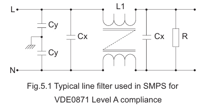
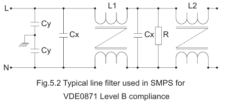
All varying electric currents and magnetic fields generate Electro Magnetic Interference. The more rapid the variation, the higher the amplitude and the broader is the frequency band of the noise emissions generated. Because they employ fast switching transitions at high power, switch mode power supplies are a major source of broad band noise. In consequence they tend to incorporate comprehensive line input filters. Typically these filters are similar to those illustrated in Fig.5.1 and 5.2 for level A and level B compliance respectively.
5.5 Limits for mains terminal interference
Power conversion product manufacturers and users are mainly concerned with the following standards.
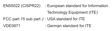
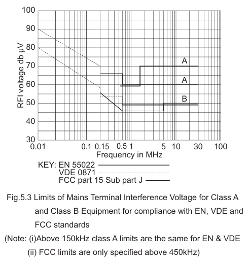
The German standards VDE0871 level A and B have for many years been used as a world wide benchmark especially for line conducted interference levels. This is partly because authorities in Germany have been able to enforce the regulations successfully as a result of legal backing, and partly because they are more stringent than CISPR standards at lower frequencies. They include limits for line conducted noise in the 10kHz to 150kHz frequency band which are of particular concern to designers of switch mode power supplies. EN55022 has no requirements below 150kHz, although from 150kHz class B limits are slightly lower (see Fig.5.3) than VDE0871. For class A equipment they coincide from 150kHz to 30MHz. FCC class A and class B limits cover the frequency spectrum from 450kHz to 30MHz, and as can be seen from Fig.5.3 the requirements are less stringent.
In common with other EC member states Germany will have to harmonize its national standards with the EN standards. The equivalent to EN55022 has been published as VDE0878 part 3 but with a national supplement part 30 which retains the low frequency conducted noise limits per VDE0871.