The widespread use of electronic equipment has increased the number of systems that use switching power supplies with capacitor‑input rectifiers, phase‑controlled circuits, and inverter‑based control systems. As a result, large amounts of distorted current now flow through commercial power lines.
Power generation and distribution equipment—such as transformers and capacitors—is originally designed to operate at 50–60 Hz. When distorted current flows into these systems, harmonic currents (integer multiples of the 50–60 Hz fundamental frequency) are generated, increasing losses in the equipment.
These losses can cause equipment failures or reduce the amount of power that can be delivered. As a result, more energy is wasted, and additional power plants must be operated unnecessarily, creating a social issue.
(1) Causes of Harmonic Currents
An ideal sine wave contains only a single frequency component.
In contrast, an ideal square wave contains a very wide range of frequency components, from a DC component up to infinitely high frequencies.
A distorted wave, which lies between these two extremes, consists of the fundamental frequency combined with all additional frequency components present up to the highest frequency contained in the waveform.
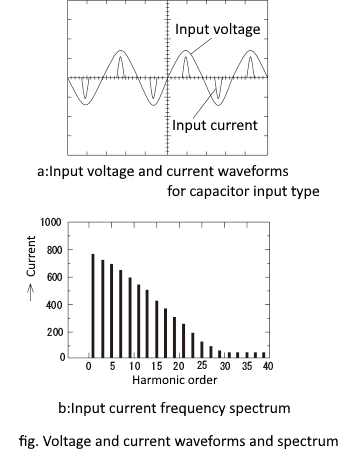
In switching power supplies that use a capacitor‑input type, the input current becomes a distorted waveform. As a result, it contains not only the 50/60 Hz fundamental component but also its integer-multiple harmonics and even higher-frequency components.
In equipment where the current waveform is sinusoidal, the power factor is determined by the phase difference between voltage and current. However, even when there is no phase difference, a distorted current waveform causes the apparent power and the real power to differ, which results in a power factor of less than one.
Therefore, suppressing harmonic currents leads to an improvement in power factor.
(2) Reduction of harmonic currents
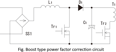
A common method for shaping the input current of a switching power supply into a sine wave is to use a dedicated boost converter that raises the full‑wave rectified voltage to the level of the smoothing capacitor.
(3) Harmonic current regulation standards
International efforts to suppress harmonic currents have been led primarily by the IEC. Since the publication of IEC 555‑2 in 1982, the standard has undergone revisions, and it has now been replaced by IEC 61000-3-2.
In Europe, EN 61000-3-2:2000/A2:2005 was issued and has been in force since September 1, 2005.
① Equipment Classes
The equipment classifications defined in EN 61000-3-2 are as follows:
| Class A |
|
|---|---|
| Class B |
|
| Class C |
|
| Class D | Equipment with an input power exceeding 75 W and exhibiting the specified special waveform (a pulsed current waveform)
|
② Limits for each class
The values in the table are given for an input voltage of 230 V.
For other input voltages, the values shall be scaled inversely with the input voltage.
Table6.1 Class A - Harmonic Current Limits
| No. | Harmonic Order n |
Maximum Permissible Harmonic Current [A] |
|---|---|---|
| Odd Harmonics | ||
| 1 | 3 | 2.30 |
| 2 | 5 | 1.14 |
| 3 | 7 | 0.77 |
| 4 | 9 | 0.40 |
| 5 | 11 | 0.33 |
| 6 | 13 | 0.21 |
| 7 | 15≤n≤39 | 0.15×15/n |
| Even Harmonics | ||
| 1 | 2 | 1.08 |
| 2 | 4 | 0.43 |
| 3 | 6 | 0.30 |
| 4 | 8≤n≤40 | 0.23×8/n |
* Class B is 1.5 times larger than Class A
Table6.2 Class C - Harmonic Current Limits
| No. | Harmonic Order n |
Maximum Permissible Harmonic Current (% of fundamental input current) [%] |
|---|---|---|
| 1 | 3 | 30×λ *1 |
| 2 | 5 | 10 |
| 3 | 7 | 7 |
| 4 | 9 | 5 |
| 5 | 11≤n≤39 | 3 |
| Even Harmonics | ||
| 1 | 2 | 2 |
*1 λ(lambda) represents the power factor of the equipment.
Table6.3 Class D - Harmonic Current Limits (Expressed in mA/W)
| No. | Harmonic Order n |
Maximum Current per Watt [mA/W] |
Maximum Permissible Harmonic Current at 230 V [A] |
|---|---|---|---|
| 1 | 3 | 3.4 | 2.30 |
| 2 | 5 | 1.9 | 1.14 |
| 3 | 7 | 1.0 | 0.77 |
| 4 | 9 | 0.5 | 0.40 |
| 5 | 11 | 0.35 | 0.33 |
| 6 | 13≤n≤39 | 3.85/n | Same as Class A |
③ Equipment exempt from the limits
- Equipment with an input current exceeding 20 A per phase
- Lighting equipment with a rated power of 5 W or less
- Standalone general-purpose inverters or servo amplifiers (when used independently)
- Machines or equipment that include inverters or servo amplifiers rated above 20 A