(1) Failure mode
In the short period immediately after a device begins operation, the failure rate tends to be higher due to latent defects in components. This phase is known as the infant mortality period. In the past, when component reliability was not as high as it is today, aging (burn‑in) was an effective way to eliminate these early failures. However, with recent improvements in component reliability and manufacturing quality, the types of early failures that can be detected through short burn‑in periods of only a few days have become increasingly rare.
Following the infant mortality period, products enter the random failure period, during which failures occur unpredictably. Due to improvements in design quality, manufacturing quality, and component reliability, the failure rate during this period has continued to decrease over the years. As components approach the end of their useful life, they transition into the wear‑out failure period, where wear‑related failures become more prominent. In general, when referring to “failure rate,” it most commonly indicates the failure rate during the random failure period.
Methods for calculating the failure rate of power supplies include approaches that estimate failures by summing predetermined component failure rates and approaches based on actual field data. A representative example of the former is reliability prediction based on MIL‑HDBK‑217, which includes both the Parts Count Method, where derating is not considered, and the Parts Stress Method, which calculates failure rates for each individual component based on its operating conditions, such as temperature, voltage, and current.
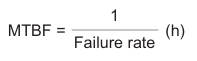
(2) MTBF
Mean Time Between Failure. The failure rate of a power supply, expressed in hours, established by the actual operation or calculation from a known standard such as MIL-HDBK-217 or RCR9102 (JEITA Standard ... Japan Electronics and Information Technology Industries Association standard).
(3) Operating temperature and Life expectancy
① The expected lifetime of a power supply
The expected lifetime of a power supply is mainly determined by the lifetime of its aluminum electrolytic capacitors. In forced‑air‑cooled models, both the capacitors and the cooling fan affect lifetime, and the component with the shorter life defines the overall lifespan of the power supply.
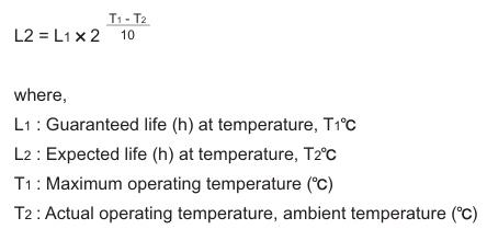
② The lifetime of an electrolytic capacitor
The lifetime of an electrolytic capacitor depends on the remaining electrolyte and the evaporation rate through the rubber seal, which is strongly influenced by temperature. Its life is therefore governed by the capacitor’s design and the thermal conditions of its operating environment. Lower operating temperatures significantly extend power‑supply life. Adequate cooling and load derating help suppress internal temperature rise. The capacitor’s operating temperature should be considered as an annual average.
③ The lifetime of a cooling fan
The lifetime of a cooling fan is affected by temperature, humidity, and dust, which accelerate bearing wear and lubricant deterioration. High temperatures or the intrusion of moisture or dust increase friction and shorten the fan’s service life.
In dusty environments, please use an air filter or similar measures to maintain cooling performance. Since the fan is a consumable part, periodic replacement based on its expected lifetime is recommended.
(4) Reliability Tests
Reliability tests are conducted to predict or confirm failures and service life of power supplies in the field. However, because accelerated testing is unavoidable, test conditions do not always match actual field conditions, and engineering judgment based on past experience is required.
The following reliability tests are performed as appropriate for each power supply:
a. High-temperature storage test
b. Temperature cycling test
c. Thermal shock test
d. THB (Temperature, Humidity, Bias) test
e. Pressure cooker test
f. Long-term operating test
g. Vibration test
h. Shock test
(5) Environment
General power supplies are designed for “Ground, Benign” environments as defined in MIL standards.
Therefore, when they are used in the following types of environments, appropriate countermeasures should be taken.
a. Ambient Temperature
Operation up to the temperatures shown in the derating curve is possible, but the impact on lifetime should be considered.
Continuous full-load operation at high temperature reduces the lifetime of power supplies using electrolytic capacitors to approximately 20,000–40,000 hours. In such conditions, forced‑air cooling or additional output derating is recommended (except for units with Teflon‑sealed capacitors).
Long-term operation at elevated temperatures can affect reliability; therefore, further derating of ambient and component temperatures is advisable for high‑reliability or continuous-operation applications.
b. Corrosive Gases
In environments containing corrosive gases such as hydrogen sulfide, sulfur dioxide, or chlorine, circuit patterns and resistors may corrode, causing open or short failures.
Similar issues can occur in environments where chlorine ions are dispersed into the air, such as when using humidifiers that operate with tap water.
c. Liquids
Ensure that conductive liquids do not come into contact with the power supply by considering its installation location and orientation.
d. Dust
Dust accumulation can impair heat dissipation, leading to failures or reduced lifetime. Use filters or other measures to prevent dust intrusion. In some environments, conductive metal or carbon particles may be present, and special caution is required for forced‑air‑cooled power supplies.
Moisture on accumulated dust can cause migration or short circuits, so operating conditions should be carefully considered.