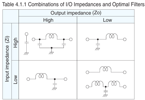
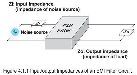
(1) Input and Output Impedance and Filter Circuit
The input and output impedances of a noise source and load determine which filter circuit is most effective.
General EMI filters use a low-pass filter configuration composed of L and C elements. If the expected attenuation cannot be achieved, the impedances of the noise source or load may be the cause.
(2) EMI Filter Installation and Orientation
Generally, an EMI filter is installed with the LINE terminal connected to the input side, but it can also be used in the reverse orientation.
However, the attenuation performance may differ when used in reverse.
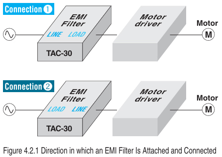
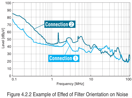
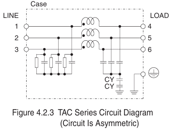
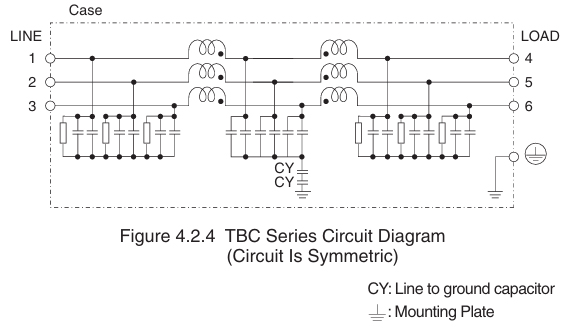
If the internal circuit is a symmetrical EMI filter (such as those in the NBC or TBC series), the orientation of the connection does not affect the noise attenuation. However, for asymmetrical filters, the attenuation may differ depending on the orientation.
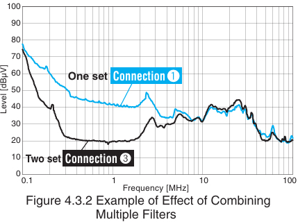
(3) Combining Multiple EMI Filters
If a single EMI filter cannot provide sufficient attenuation, the attenuation performance can be improved by connecting two filters in series. However, note that doing so will also combine the leakage current and voltage drop of both filters.
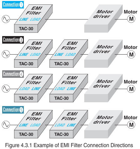
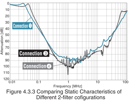
When two EMI filters are connected in series, the orientation of each filter may also affect the attenuation characteristics.
Figure 4.3.3 shows a comparison of the attenuation characteristics (static characteristics) for different connection orientations.
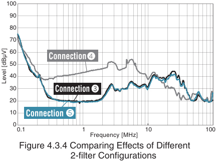
Figure 4.3.4 shows the actual noise characteristics measured for each orientation.
In this case, unlike the static characteristic data, connection ④ does not improve attenuation.
This occurs because the input and output impedances of the EMI filters in the actual equipment differ from the conditions used for the static measurements. To optimize the connection of EMI filters, it is necessary to evaluate the configuration by measuring the actual noise levels in the system.
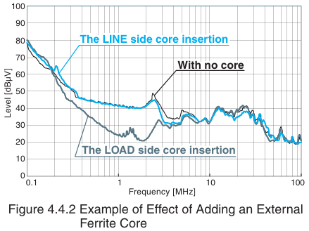
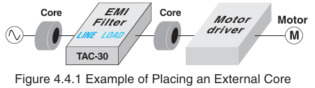
(4) External Ferrite Core
If one EMI filter cannot provide sufficient attenuation, the effect can be improved by inserting an external core. Whether a core is inserted on the LINE side or on the LOAD side of an EMI filter may cause difference in the attenuation characteristic.
When adding a core on the LINE side, one needs a core that can generate sufficiently large inductance for the choke coil within the EMI filter.
Just inserting on the LINE side a core whose performance is equal to or less than that of the internal choke coil does not contribute to reducing noise.
When inserting it on the LOAD side, it will produce a large attenuation effect because the circuit takes a configuration of a T-type EMI filter circuit.