(1) Rated Voltage
The rated voltage is the maximum nominal line voltage at which the EMI filter can be used.
However, because many internal components have higher voltage ratings, the filter may operate without issues even if the actual voltage slightly exceeds its rated value.
Some EMI filters also specify a maximum operating voltage separately from the rated voltage.
Using the filter at voltages lower than its rating is not a problem. For example, a filter rated at AC 250 V can be used on AC 100 V lines.
EMI filters for AC power lines are generally designed for commercial frequencies (50 Hz / 60 Hz).
Higher frequencies, such as 400 Hz, may cause excessive heating of the internal capacitors, so caution is required.
Note that EMI filters for AC power lines can also be used on DC power lines.
(2) Rated Current
The rated current is the maximum load current (nominal value) that can be continuously carried. If the ambient temperature is high, however, the load current needs to be derated.
Figure 2.2.1 shows an example of a derating characteristic.
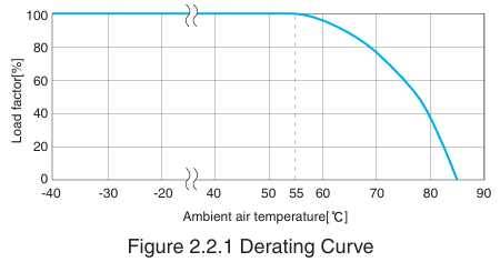
This example indicates that when the maximum ambient temperature reaches 75°C, the EMI filter should be used with a load factor of approximately 60% (about 60% of the rated current) or less.
EMI filters can tolerate currents higher than their rated current only for short periods. Inrush currents-such as those from typical switching power supplies (up to 40 A or about ten times the rated current, occurring as single pulses lasting a few milliseconds)-generally do not cause any issues.
However, if the peak current lasts longer or occurs repeatedly, the average current may exceed the filter’s rating, and the operating conditions must be reviewed.
(3) Test Voltage (Withstand Voltage)
The test voltage is the voltage applied during a withstand voltage test. This test confirms that the EMI filter does not experience insulation breakdown when a high voltage is applied for a short time between a terminal (line) and the mounting plate (ground).
For EMI filters used on AC power lines, the test voltage is typically AC 2000 V or AC 2500 V.
During the withstand voltage test, the high voltage applied between the line and ground causes much higher leakage current than in normal operation. When performing this test during acceptance inspection, please set the cutoff current of the tester to the value specified for the EMI filter.
For EMI filters with especially large ground‑capacitor values, DC voltage is used instead of AC because AC voltage would generate excessive leakage current.
(4) Insulation Resistance (Isolation Resistance)
Insulation resistance is the resistance measured when a specified DC voltage (typically 500 V) is applied between isolated conductors, such as a terminal (line) and the mounting plate (ground). It is used as one indicator of the degree of insulation.
The insulation resistance is determined by measuring the very small current that flows through insulating materials-such as the resin case or capacitors—when the DC voltage is applied.
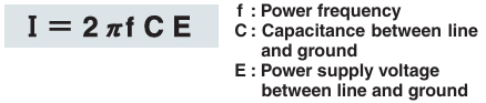
(5) Leakage Current
The leakage current is the current that flows from the ground terminal of an EMI filter when the filter is connected to an AC power line.
In general, increasing the capacitance of the ground capacitor enhances the reduction of common-mode noise, but it also increases the leakage current.
Care must be taken because excessive leakage current may cause a circuit breaker to trip, and if the EMI filter is not properly grounded, it may even lead to electric shock.
The current (I) that flows from each power line to ground can be expressed by the following equation, which serves as the basis for calculating leakage current.
(6) DC Resistance
DC resistance is the resistance measured between the input and output of an EMI filter (the total resistance in both directions).
It is mainly determined by the coil winding resistance, but also includes the resistance of the connections between the coils and the terminals.
The voltage drop caused by an EMI filter can be expressed by the following equation:

Note that for some products, the specifications define the voltage drop at the rated current rather than the resistance value.
(7) Temperature/Humidity
a. Operating temperature
This is the range of ambient temperatures within which the product is guaranteed to operate properly.
When the ambient temperature is high, the load current must be derated.
b. Operating humidity
This is the range of ambient humidity levels for which the product’s operation is guaranteed.
Operation is assumed to occur without condensation.
c. Storage temperature and humidity
These are the allowable ranges of ambient temperature and humidity in which EMI filters can be stored in an unpowered state without performance degradation.
As with operating humidity, storage humidity also assumes no condensation.
(8) Circuitry
The following show examples of EMI filter circuit structures.
a. Single-phase 1-stage filter
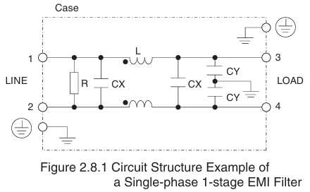
This figure shows a typical circuit configuration for single-phase EMI filters.
L and CY reduce common-mode noise, while CX and the leakage inductance of L reduce normal-mode noise.
R represents the discharge resistor for the capacitors.
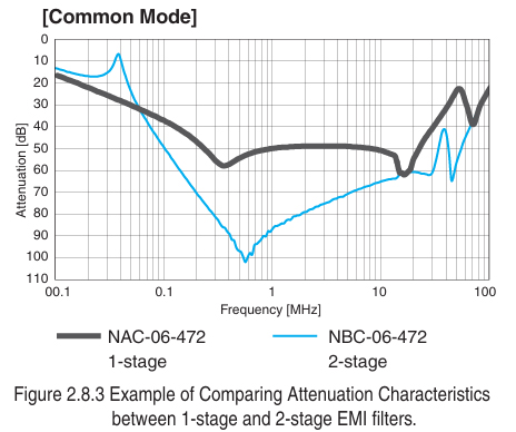
b. Single-phase 2-stage EMI filter
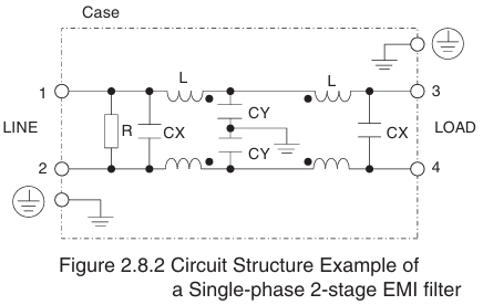
The figure above shows an example of a two‑stage choke‑coil configuration designed to improve attenuation characteristics.
The following graph shows a comparison of the attenuation characteristics of one-stage and two-stage EMI filters.
(9) Safety Standards
a. General description of safety standards
International safety standards consist mainly of IEC standards, which apply to electrical fields, and ISO standards, which apply to non-electrical fields.
IEC (International Electrotechnical Commission)
The IEC is a standards organization responsible for developing international standards related to electrical and electronic technologies. It is headquartered in Switzerland.
The IEC publishes technical standards based on the latest science and technology, and individual countries develop their own safety standards based on the corresponding IEC standards.
CISPR (Comite International Special des Perturbations Radioelectriques =International Special Committee on Radio Interference)
CISPR is one of the IEC’s specialized committees.
It was established to unify standards-such as limits and measurement methods-for electromagnetic interference that can affect radio communications, and it includes the standardization committee for EMC (Electromagnetic Compatibility).
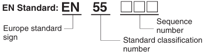
European Standard / EN Standard (Europäische Norm)
EN standards are based on IEC and CISPR standards and generally contain requirements similar to those found in both.
Each EN standard is assigned its own unique number.
(Example:IEC60939 EN60939)
An example of Certification Authorities in Europe based on EN Standard
| VDE | Germany |  |
|---|---|---|
| TUV | Germany |  |
| DEMKO | Denmark |  |
| SEMKO | Sweden |  |
| Standard classification number | Reference standards |
|---|---|
| EN50000 series | General European standards |
| EN55000 series | CISPR standards |
| EN60000 series | IEC standards |
ENEC (European Norm Electrical Certification)

The ENEC mark is a European safety approval mark that allows products to be distributed smoothly among all EU member states, EFTA countries, and Eastern European countries.
Electronic products authorized to bear the ENEC mark do not require additional approval procedures within these countries, eliminating the need to obtain separate approvals from each individual signatory.
The ENEC mark applies to products such as lighting equipment, transformers, information-processing equipment, switches, and EMI filters.
| EU signatories | Germany, UK, Italy, Denmark, and 24 other countries |
|---|---|
| EFTA | Iceland, Norway, Switzerland, and Liechtenstein |
| East European countries | Ukraine, Estonia, Belarus, Moldova, Latvia, and Lithuania |
North America
UL (Underwriters Laboratories Inc.)
UL is a testing organization established in 1894 by the Electrical Bureau of the National Board of Fire Underwriters. Since its founding, UL has conducted compliance testing on a wide range of electrical products.
CSA (Canadian Standard Association)
CSA is a non‑profit standards organization established in Canada in 1919.
Canadian provincial laws require that electrical equipment connected to public power sources conform to CSA standards.
| UL | USA |  |
|---|---|---|
| CSA | Canada |  |
As the United States and Canada have signed an MRA (Mutual Recognition Agreement), mutual approval can be granted. If UL verifies that an electrical product conforms to CSA standards, or to both UL and CSA standards, the product is authorized to bear the following approval marks:
| CSA |  |
|---|---|
| UL / CSA |  |
b. Safety standards for EMI filters
Different products may conform to different safety standards and bear different approval marks, depending on the countries in which they are used. Be sure to check the applicable safety approvals when selecting a product.
| IEC939 | International standard IEC |
|---|---|
| EN60939 | EU EN |
| UL1283 | USA UL |
| C22. 2 No.8 | Canada CSA |
c. CCC approval from China
EMI filters do not fall within the scope of CCC. (as of November 2011)
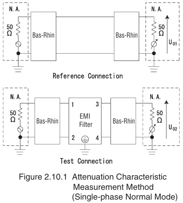
(10) Attenuation Characteristic (Static Characteristic)
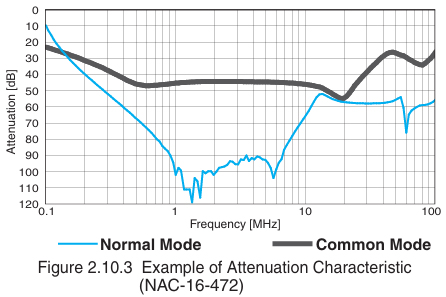
Attenuation characteristics provide a general indication of the noise‑reduction performance of an EMI filter. The graph is obtained by measuring the attenuation when the filter is connected to a specified measurement circuit, with frequency on the horizontal axis and attenuation on the vertical axis.
The measurement methods are shown in Figures 2.10.1 and 2.10.2. Attenuation is defined as the ratio of U01 to U02, where U01 is the output when the EMI filter is not inserted in the circuit, and U02 is the output when it is inserted. This ratio is normally expressed in decibels [dB] using its logarithmic value.
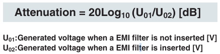
* An attenuation of 20 dB corresponds to a noise level reduced to 1/10 of that without the EMI filter.
Similarly, 40 dB and 60 dB correspond to reductions to 1/100 and 1/1000, respectively.
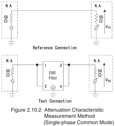
The attenuation characteristic of an EMI filter is affected by the input and output impedances of the measurement circuit.
The attenuation characteristic (static characteristic) is measured under the fixed condition that both the input and output impedances are 50 Ω, regardless of frequency. This allows the attenuation characteristics of different filters to be compared under identical conditions.
However, actual electronic equipment has different power-line impedances, and these impedances vary with frequency rather than remaining constant. For this reason, the attenuation characteristics (static characteristics) shown in EMI‑filter catalogs do not necessarily match those obtained when the filters are installed in real equipment.
It should also be noted that when EMI filters are connected in series, the resulting static characteristic is not obtained by simply adding the individual static characteristics in decibels (dB).
(11) Pulse Attenuation Characteristic
Figure 2.11.2 shows how effectively an EMI filter attenuates pulse-type common‑mode noise on a power line, which may cause malfunctions in electronic equipment. Figure 2.11.1 illustrates the measurement method.
In this test, the input and output of the EMI filter are terminated with 50 Ω. A specified pulse waveform is applied to the input, and the pulse voltage appearing at the output is measured. The results are then plotted with the input pulse voltage on the horizontal axis and the output pulse voltage on the vertical axis.
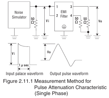
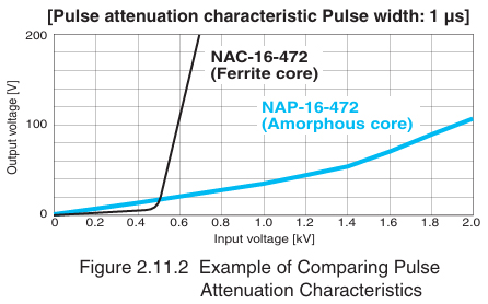
Figure 2.11.2 provides an example comparing the pulse attenuation characteristics of an EMI filter using a general ferrite core with one using an amorphous core. The graph indicates that the amorphous-core filter suppresses the increase in output pulse voltage more effectively as the input pulse voltage rises (i.e., it has better pulse attenuation performance).
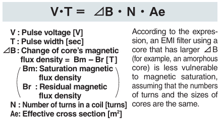
When the volt-second product of a pulse exceeds a certain threshold, the choke coil inside the EMI filter becomes magnetically saturated, causing its noise‑suppression ability to drop significantly.
The volt-time product (V·T) that leads the core to magnetic saturation can be calculated using the following expression:
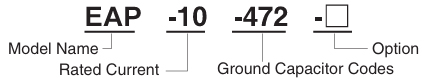
(12) Ground Capacitor Codes
Many EMI filters can accommodate different ground‑capacitor values by specifying the appropriate code.
The available ground-capacitor codes vary depending on the filter model.
The following table shows an example of ground‑capacitor codes and their corresponding attenuation characteristics.
Table 2.12.1 Example of Ground Capacitor Codes (EAP series)
| Code | Leakage Current (input 125/250V 60Hz) | Line-to-ground capacitor (nominal value) |
|---|---|---|
| 000 | 5μA / 10μA max | Not Provided |
| 101 | 12.5μA / 25μA max | 100pF |
| 221 | 25μA / 50μA max | 220pF |
| 331 | 37.5μA / 75μA max | 330pF |
| 471 | 50μA / 100μA max | 470pF |
| 681 | 75.5μA / 150μA max | 680pF |
| 102 | 0.13mA / 0.25mA max | 1000pF |
| 222 | 0.25mA / 0.5mA max | 2200pF |
| 332 | 0.38mA / 0.75mA max | 3300pF |
| 472 | 0.5mA / 1.0mA max | 4700pF |
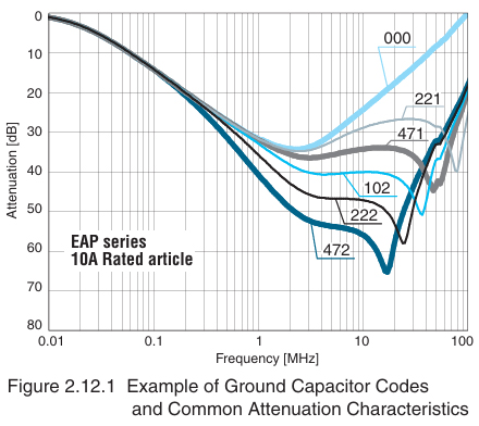
Generally, the larger the ground-capacitor value, the better the common-mode attenuation.
However, the leakage current also increases, so there is a trade-off.
With a wide range of ground-capacitor options, it is possible to choose the value that provides the best balance between attenuation performance and leakage current.
(13) Options
Our EMI filters can be customized by specifying an option code.
Because the available options differ depending on the filter model, please refer to our catalog for details.
The following describes each option:
a. DIN rail installation type: D
This option allows the EMI filter to be mounted on a DIN rail, which is commonly used in control panels and similar equipment.
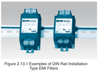
Note that grounding through the DIN rail alone may not provide adequate noise attenuation.
Be sure to connect the ground to the protective earth (PE) terminal of the EMI filter.
For EMI filters with two protective earth terminals, the ground may be connected to either one.
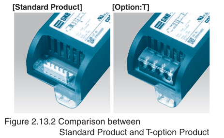
b. Terminal block type: T
These types of EMI filters use a terminal block as their interface (instead of the connector used in the standard product).
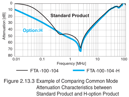
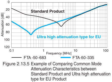
c. High permeability choke coil type (ultra low-frequency and ultra high attenuation): H
These types of EMI filters use a choke-coil core with high permeability.
These types provide improved common-mode attenuation at low frequencies compared with the standard products.
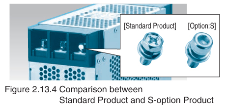
d. Hex socket head cap bolt type: S
These types of EMI filters use a hexagon socket head cap (Allen) bolt in their terminal block instead of the standard cross-recessed (Phillips) hexagon head bolt.
This allows customers to select the type of bolt that matches the tools they use.
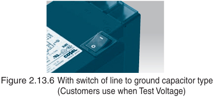
e: With switch of line to ground capacitor type : G
These types are ultra-high-attenuation models for the EU and are equipped with a switch for the line-to-ground capacitor.
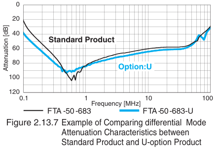
f. Improve differential mode attenuation type : U
These types have their rated voltage changed to 250 V.
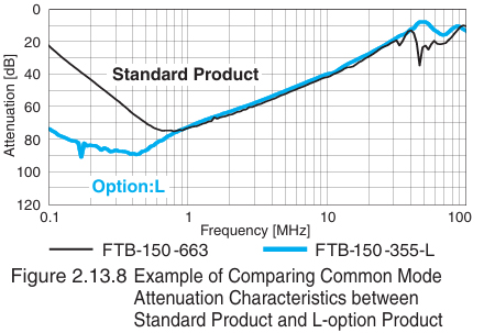
g. Ultra high attenuation type for EU : L
These types are ultra-high-attenuation models for the EU.
h. High input voltage : F
These types have their rated voltage changed to 500 VAC / 600 VDC.
Option code is possible combination.
Please contact us for more information.