Q&A(FAQ) Operation tutorial of Voltage doubler circuit
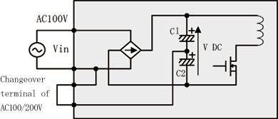
In power supplies equipped with a voltage-doubler rectifier, the input voltage is rectified by the voltage-doubler circuit when the AC100/200V changeover terminal is set to AC100V. Conversely, when the changeover terminal is set to AC200V, the input voltage is rectified by a full-wave rectifier circuit.
The operation of the voltage-doubler rectifier circuit is shown below.
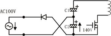
The voltage-doubler rectifier circuit is shown in Fig. 1, and the current path differs depending on whether the input voltage is positive or negative.
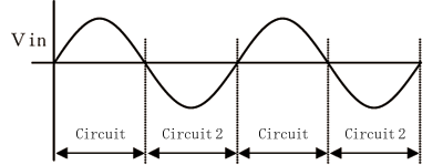
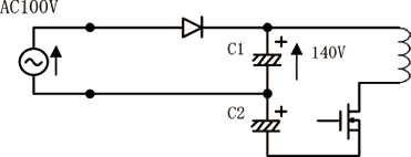
When the input voltage is positive, the circuit shown in Fig. 2 operates and charges C1. Conversely, when the input voltage is negative, the circuit shown in Fig. 3 operates and charges C2.
Therefore, V-DC—the voltage of C1 and C2 combined—will always be maintained at approximately 280 VDC in both AC100V and AC200V operation, and the internal voltage of the power supply will remain at a constant level.