Free warranty period 3-year
Harness,Fan unit
| Type | Model number | Description | DXF | |
|---|---|---|---|---|
| Terminal Attachment | ||||
| B-ACE-7 | Terminal attachment to facilitate faston terminal output modules. | PDF download | - | |
| B-ACE-8 | Terminal attachment to facilitate wiring. | PDF download | - | |
| B-ACE-9 | Terminal attachment for series operation as output modules. | PDF download | - | |
| Fan unit | ||||
| FAN-AC4 | Fan unit for ACE450/650F. (Standard model) |
PDF download | - | |
| FAN-AC4-F | Fan unit for ACE450/650F. (F option : Reversed air flow) |
PDF download | - | |
| FAN-AC4-K | Fan unit for ACE450/650F. (K option : Lower speed fan) |
PDF download | - | |
| FAN-AC4-T | Fan unit for ACE450/650F. (T option : With dust filter) |
PDF download | - | |
| Harness | ||||
| H-SN-14 | Harness for using AUX and PR alarm of CN1. | PDF download | - | |
| H-SN-16 | Harness for using all functions of output modules. (CN2) | PDF download | - | |
| H-SN-17 | Harness for using all functions except remote sensing of output modules. (CN2) | PDF download | - | |
| H-SN-18 | Please refer catalog of applicable model for usage. | PDF download | - |
*Some documents may not be listed. Please contact us for more details.
| CAD data | DXF |
Standard model
|
|---|---|---|
| 3D CAD data | STEP |
Standard model
|
| IGES |
Standard model
|
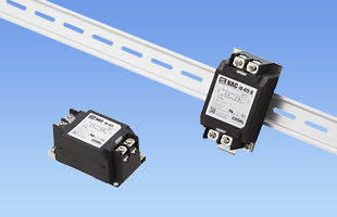
Single phase 250VAC 10A
General purpose
High-attenuation type from 150kHz to 1MHz
1-stage filter
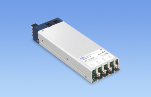
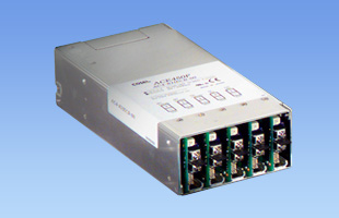
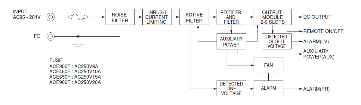
Rated Input: 85 - 264VAC 1Φ
Rated Output Wattage: 600W
Slots: 4
Rated Output Voltage: 3.3V, 5V, 7.5V, 12V, 15V, 24V, 36V, 48V, 65V, 75V, 100V, 24V/24V
AC(1) □(2) - □(3) □(4) □(5) □(6) □(7) □(8) - □□(9) - □□(10)
(1) Abbreviation type name of ACE series*For detailed specifications and usage guidelines, please refer to the catalog and instruction manual.
| Item | Specification | |||||
|---|---|---|---|---|---|---|
| Module code | L | M | N | P | R | |
| Slots used | 1 | 1 | 1 | 1 | 1 | |
| Output | Power | 33 W | 50 W | 60 W | 60 W | 60 W |
| Voltage / current | 3.3 V 10 A | 5 V 10 A | 12 V 5 A | 15 V 4 A | 24 V 2.5 A | |
| Voltage adjustment range | 2.60 to 3.60 V | 4.00 to 5.50 V | 9.00 to 13.2 V | 13.2 to 16.5 V | 19.2 to 26.4 V | |
| Built-in functions | Overcurrent protection |
Activates at 105% min of rated current, automatic recovery.
|
||||
| Overvoltage protection | 4.00 to 5.25 V | Activates at 115 to 140% of rated voltage. | ||||
| Remote control |
Available
|
|||||
| Remote sensing |
—
|
|||||
| Other |
—
|
|||||
| Item | Specification | |||||||||||||
|---|---|---|---|---|---|---|---|---|---|---|---|---|---|---|
| Module code | A | B | C | D | E | F | G | H | J | K | ||||
| Slots used | 1 | 1 | 1 | 1 | 1 | 1 | 1 | 1 | 1 | 1 | ||||
| Output | Power | 52 W | 85.8 W | 130 W | 135 W | 156 W (peak 168 W) |
150 W (peak 180 W) |
153 W (peak 180 W) |
156 W (peak 192 W) |
153 W (peak 187 W) |
153.6 W (peak 192 W) |
|||
| Voltage / current | 2 V 26 A | 3.3 V 26 A | 5 V 26 A | 7.5 V 18 A | 12 V 13 A (peak 14 A) |
15 V 10 A (peak 12 A) |
18 V 8.5 A (peak 10 A) |
24 V 6.5 A (peak 8 A) |
34 V 4.5 A (peak 5.5 A) |
48 V 3.2 A (peak 4 A) |
||||
| Voltage adjustment range | 1.60 to 2.60 V | 2.60 to 3.60 V | 4.00 to 5.50 V | 6.00 to 8.20 V | 9.00 to 13.2 V | 13.2 to 16.5 V | 16.5 to 19.2 V | 19.2 to 26.4 V | 27.2 to 37.4 V | 38.4 to 52.8 V | ||||
| Built-in functions | Overcurrent protection |
Activates at 105% min of rated current; models with peak current activate at 101% min of peak current, automatic recovery.
|
||||||||||||
| Overvoltage protection | 3.00 to 4.80 V | 4.00 to 5.25 V | Activates at 115 to 140% of rated voltage. | |||||||||||
| Remote control |
Available
|
|||||||||||||
| Remote sensing |
Available
|
|||||||||||||
| Other |
—
|
|||||||||||||
| Item | Specification | |||||||||||||
|---|---|---|---|---|---|---|---|---|---|---|---|---|---|---|
| Module code | 2A | 2B | 2C | 2D | 2E | 2F | 2G | 2H | 2J | 2K | ||||
| Slots used | 2 | 2 | 2 | 2 | 2 | 2 | 2 | 2 | 2 | 2 | ||||
| Output | Power | 120 W | 198 W | 300 W | 300 W | 300 W (peak 408 W) |
300 W (peak 405 W) |
306 W (peak 414 W) |
336 W (peak 480 W) |
340 W (peak 476 W) |
336 W (peak 480 W) |
|||
| Voltage / current | 2 V 60 A | 3.3 V 60 A | 5 V 60 A | 7.5 V 40 A | 12 V 25 A (peak 34 A) |
15 V 20 A (peak 27 A) |
18 V 17 A (peak 23 A) |
24 V 14 A (peak 20 A) |
34 V 10 A (peak 14 A) |
48 V 7 A (peak 10 A) |
||||
| Voltage adjustment range | 1.60 to 2.60 V | 2.60 to 3.60 V | 4.00 to 5.50 V | 6.00 to 8.20 V | 9.00 to 13.2 V | 13.2 to 16.5 V | 16.5 to 19.2 V | 19.2 to 26.4 V | 27.2 to 37.4 V | 38.4 to 52.8 V | ||||
| Built-in functions | Overcurrent protection |
Activates at 105% min of rated current; models with peak current activate at 101% min of peak current, automatic recovery.
|
||||||||||||
| Overvoltage protection | 3.00 to 4.80 V | 4.00 to 5.25 V | Activates at 115 to 140% of rated voltage. | |||||||||||
| Remote control |
Available
|
|||||||||||||
| Remote sensing |
Available
|
|||||||||||||
| Other |
—
|
|||||||||||||
| Item | Specification | ||||
|---|---|---|---|---|---|
| Module code | Y | W | Z | 9 | |
| Slots used | 1 | 1 | 1 | 1 | |
| Output | Power* | 50 W | 76.8 W | 75 W | 76.8 W |
| Voltage | ±5 V | ±12 V | ±15 V | ±24 V | |
| Current 1* | 3 A | 3.2 A | 2.5 A | 1.6 A | |
| Current 2* | 7 A | 4.2 A | 3.5 A | 2.5 A | |
| Peak current* | — | 5 A | 4 A | — | |
| Voltage adjustment range | 4.99 to 6.00 V | 9.60 to 13.2 V | 13.2 to 16.5 V | 19.2 to 26.4 V | |
| Built-in functions | Overcurrent protection |
Activates at 105% min of rated current; models with peak current activate at 101% min of peak current, automatic recovery.
|
|||
| Overvoltage protection | 6.90 to 8.40 V | 13.8 to 16.8 V | 17.25 to 21.0 V | 27.6 to 33.6 V | |
| Remote control |
Available
|
||||
| Remote sensing |
—
|
||||
| Other |
—
|
||||
| Item | Specification | ||
|---|---|---|---|
| Module code | Q | V | |
| Slots used | 1 | 1 | |
| Output | Power* | 153.6 W | 165 W |
| Voltage | ±12 V | ±15 V | |
| Current 1* | 6.4 A | 5.5 A | |
| Current 2* | 8 A | 7 A | |
| Peak current* | 10 A | 8 A | |
| Voltage adjustment range | 9.60 to 13.2 V | 13.2 to 16.5 V | |
| Built-in functions | Overcurrent protection |
Activates at 105% min of rated current; models with peak current activate at 101% min of peak current, automatic recovery.
|
|
| Overvoltage protection | Activates at 115 to 140% of rated voltage. | ||
| Remote control |
Available
|
||
| Remote sensing |
—
|
||
| Other |
—
|
||
| Item | Specification | ||||||
|---|---|---|---|---|---|---|---|
| Module code | S | T | U | ||||
| Slots used | 1 | 1 | 1 | ||||
| Output | Power | 75 W | 100.4 W | 100.4 W | |||
| Voltage / current | V1: 5 V 10 A |
V2: 5 V 5 A |
V1: 5 V 10 A |
V2: 12 V 4.2 A |
V1: 5 V 10 A |
V2: 24 V 2.1 A |
|
| Voltage adjustment range | 4.99 to 5.50 V | 3.00 to 5.50 V | 4.99 to 5.50 V | 7.50 to 13.2 V | 4.99 to 5.50 V | 15.0 to 26.4 V | |
| Built-in functions | Overcurrent protection |
Activates at 105% min of rated current, automatic recovery.
|
|||||
| Overvoltage protection |
Activates at 115 to 140% of rated voltage.
|
||||||
| Remote control |
Available
|
||||||
| Remote sensing |
—
|
||||||
| Other |
—
|
||||||
*For detailed specifications and usage guidelines, please refer to the catalog and instruction manual.
Input terminal orientation can be changed to match the output module side by using the "I module" option. See the catalog / instruction manual for details.